GOLFMK8
GOLFMK7
GOLFMK6
GOLFMKV

How to retro-fit the traction control (ESC) button to a Mk7 Golf

golfdave

Autocross Champion
Location
Scotland (U.K.)
Car(s)
Mk7 Golf GT Estate
Im resurrecting the topic....
I have a question kinda related to the subject. Im trying to retrofit ESC button on a different VAG but the factory offers only 2 switches and none of them has all buttons.
The switch has an electric board with a chip carrier that has pins to connect with the 10pin plug (6R0972930).
Each available switch from VW has different pins on the electric board.
My question is....if possible to install more pins so I can retrofit the button from one switch to the other. An LED surely can be soldered. I believe those chip carriers are the same.
Sorry for the confusion. Im no expert.

With some skill & a small tipped soldering iron you could possibly de-solder the parts of the switch from one board & re-fit them onto the other board...
 

xvibes

New member
Location
Greece
Car(s)
POLO GTI 1.8lt Gen3
With some skill & a small tipped soldering iron you could possibly de-solder the parts of the switch from one board & re-fit them onto the other board...
I started the process....those switches are a pain to disassemble.
I dont think Im qualified to remove the pins hahaha (they are the same position like on MK7 9-10)
Now Im waiting for a spare switch cause I wanna damage the one on the car.
"In theory" I'll remove the White LED and the pins. They are header pins so they should be easier to desolder.
Thanks again for everything this topic was very helpful.
 

Attachments

  • 20230116_201539A.jpg
    20230116_201539A.jpg
    2.9 MB · Views: 76
  • 20230116_201736A.jpg
    20230116_201736A.jpg
    1.1 MB · Views: 74
  • 20230116_211010.jpg
    20230116_211010.jpg
    1.1 MB · Views: 77

Estland

New member
Location
Estonia
Car(s)
Mk7
Hello I followed the instructions and the button is working fine using pins 9 and 10.

Should the ESC button also illuminate in yellow color like the Start-Stop system button when pushed? (Mine doesn't)
 

golfdave

Autocross Champion
Location
Scotland (U.K.)
Car(s)
Mk7 Golf GT Estate
Hello I followed the instructions and the button is working fine using pins 9 and 10.

Should the ESC button also illuminate in yellow color like the Start-Stop system button when pushed? (Mine doesn't)

No it only lights up white with the dash lighting..it does not light up orange when you press it..
 

mayday_soc

New member
Location
RI
Car(s)
MK7 TDI
@golfdave If I have no switch’s on the left of my shifter but one switch on my right, can I grab illumination and ground from the switch panel on the right? If I can, do you happen to know which number wire in the pin out is lume and ground? I know I can get lume from my headlight switch, just trying to find something closer and an earth ground near by.
 

golfdave

Autocross Champion
Location
Scotland (U.K.)
Car(s)
Mk7 Golf GT Estate
@golfdave If I have no switch’s on the left of my shifter but one switch on my right, can I grab illumination and ground from the switch panel on the right? If I can, do you happen to know which number wire in the pin out is lume and ground? I know I can get lume from my headlight switch, just trying to find something closer and an earth ground near by.

I think people have taken the ground & illumination from the 3 button panel on the other side. Info should be in this thread or on the TPMS button retro fit thread here:-

https://www.golfmk7.com/forums/inde...fit-the-tpms-set-button-to-a-mk7-golf.338152/
 

Osmanozturk

New member
Location
Turkey
Car(s)
Golf 7
Part 3 of 4
Fitting

Now to undo the loom & wire up!

As I have the Autohold switch I can wire as per the factory. So with the side trim removed on the centre console the loom for the switches on this side is exposed. I located the black/yellow wire, & I carefully “pinged” out the two white plastic loom holders, then I tied some string to the switch connector & pulled it through from the gearstick area to the footwell side. This exposed the whole of this section of loom. I had to undo another t-star screw (T-20 size) fixing the centre console to a bracket (marked on photos). Then even more carefully I cut & removed all the fabric loom tape. I then scraped some insulation off the wire & connected a multi-meter to the – of the battery (actually the body point) & + to the wire & switched on & off the ignition & also removed the fuse34 & double checked that was the correct wire e.g. should be 12V when supplied & dead when cut off!

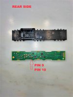
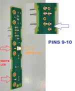
I undid the switch connector (T10ks) using a small flat screwdriver under the middle section, the flap hinges up at the back & this unlocks the pins. I then inserted one repair wire (000 979 009 E) into each of the spaces for pins 9 & 10 on the connector block & closed the locking flap. I then marked the other ends of these wires & re-wrapped these wires along with the existing wires from the switch down to the main section of the loom. Now you join the pin 10 wire to the existing loom black yellow wire & the pin 9 wire to your purple “extension wire”. So now you can cut off the surplus wire (with other pin) from each repair wire. I had a slight problem when I spliced my pin 10 wire to the black/yellow wire & had to “extend” the main wire, this can be seen by two joints on the wire in the photos! Now at this point it is advisable to test the switch, so fuse 34 back in, new switch module plugged into the connector, multi-meter -connected to car battery body – point & + connected to the other end of your purple extension wire. Ignition on 0V, press ESC OFF switch & you should have 12V momentarily. I then re-wrapped the rest of this section of loom & the white plastic loom holders.

Now to get the purple “extension” wire to the T17d in the TIUL Coupling. There is an existing wiring loom from the TIUL coupling up to the bulkhead & along the bulkhead behind the footwell carpet trim top section. I used this to run the cable along. However there is nothing suitable from the centre console to the bulkhead! So I wrapped the wire in fabric tape (enough to cover to the bulkhead) & then passed the cable through a short length of small corrugated plastic flex pipe (used in car electrical) (enough to cover to the bulkhead). I also wrapped the pipe in fabric tape to prevent rattling. I then fixed the pipe to the metal bracket on the centre console & the existing loom on the bulkhead. The pipe is just pushed under the upper section of the carpet trim & is held there under compression. This area is covered by the plastic trim you removed earlier!

Şimdi onarım kablosunu (000 979 034 E) ve mor uzatma kablonuzu kullanarak TIUL Bağlantı noktasındaki T17d konektörünü bağlayın. Öncelikle T17d konnektörü diğer bölümden çıkarmak için üst tırnağa bastırarak açın. Ardından konektör üzerindeki mor plastik kilitleme kelepçesine bakarak, her iki taraftaki "kanatları" kaldırın ve plastik kilit kelepçesini çıkarın. Bu, pimlerin kilidini açar. Şimdi onarım teli pimini boş (konektör bağlantısının bu tarafında) pim 5 konumuna yerleştirin. Plastik kilit kelepçesini değiştirin (ancak konektörü bağlamayın). Şimdi onarım telini mor "uzatma telinize" bağlayın ve ardından kablonun geri kalanını bant/kablo bağı vb.

Şimdi önceden çektiğiniz ipi kullanarak, anahtar kablo demeti konnektörüne bağlayın ve konnektörü tekrar vites kolu alanına doğru çekin. Bu biraz dikkat ve uğraş gerektirir! Ardından beyaz plastik dokuma tezgahı tutucularını deliklerine yeniden takın, kablo yönlendirmesinin güvenliğini ve düzgünlüğünü iki kez kontrol edin.

Şimdi trimi yeniden takmadan önce anahtarın çalışıp çalışmadığını iki kez kontrol edin. Bu nedenle, sigorta 34'ü (çıkarılmışsa) yeniden takın, kontak açık, anahtar gece için diğer tüm anahtarlarla birlikte yalnızca beyaz yanacaktır (asla kehribar rengi yanmaz). Düğmeye 1 saniye basın ve normalde bilgi-eğlence sistemi aracılığıyla etkinleştirildiğinde alacağınız gibi, MFD'de “Çekiş kontrolü (ASR) kapalı” ekranını görmelisiniz! Bilgi-eğlence sisteminde ASR'yi hiç devre dışı bırakmadıysanız, "CAR" menüsü altında ASR (veya ESC?) adlı yeni bir alt menü gösterilmelidir. Bir "KAPALI" seçeneği de göstermek için buna basın. Anahtarı kullanmak çok daha hızlı! Ayrıca diğer anahtarların da (varsa) çalışıp çalışmadığını kontrol edin. Artık tüm döşemeyi yeniden takabilirsiniz. Önce gri köpük trim panelini, ardından diğer öğeleri yapın.
Merhaba driver select mode için lisans satın almak gerekiyor mu? Sadece kablo tesisati ,vcds kodlama ve tuş takımi ile bu mümkün mü?
 

Cuzoe

Autocross Champion
Location
Los Angeles
Hi Dave, is there a way to do it without like melting 2 cables into 1 for 12V ? How vw did for OEM?
I don't know exactly what you mean by melting two cables into 1. If you mean splicing wires there's not much to worry about. There are factory splices all over the car's wiring.

But from the factory the 12V for this button comes from the fuse panel, in spot SC34. There are also several other things connected to the same fuse SC34, depending on the equipment in your car.

All of this is in the first post, by the way, snipped here...
At the factory this is wired as a 12V supply coming from Fuse 34 (7.5A), in a Black/Yellow wire, into the ESC switch (pin 10). Then a Purple/Green wire from the ESC switch (pin 9) into the ABS/ESC controller (pin 39).

However, halfway along this wire to the ABS/ESC controller there is a connector in the loom (connector T17d, using pin5), at what VW call the “TIUL Coupling Point”.

Your car might have the wire from the ABS unit to the TIUL Coupling point already installed, thus only requiring you to wire inside the cabin & not having to go through the firewall into the engine bay.

Before ordering any parts I suggest that you remove the trim covering the TIUL Coupling point & look at the black connector on the middle row nearest the bodywork. This should be connector “T17d”. Press the top tab & separate the connector in two. Now the side with the cables facing you is the side which goes to the switch. The part of the connector still in the holder having the cables facing away from you is the main car loom & goes to the ABS unit. This main loom MUST have a purple/green wire going into the bottom row of pins, & the fifth from the right (PIN 5). If you have this all is OK, if you don’t have this you will have to wire into the pin on the ABS unit. If you have to do this there is no need for you to wire via the TIUL coupling point which you


TIUL Coupling Point
This is a junction for up to six electrical connectors (arranged in three rows of two) in the main wiring loom, & is situated in the same place in both left & right hand drive cars. This being behind the plastic trim panel under the glove box, & next to the passenger door hinges on a UK car. Or for Europe/USA it is between the driver’s door hinges & the footrest (behind the bonnet release handle).


Fuse 34 on fuse holder C -SC34-
This is a 7.5A mini fuse on fuse panel C, in the bottom left area (behind glove box UK or driver side Europe/USA) & designated for the following items:-
Rotary light switch –EX1-,
Interior mirror -EX5-,
Relay for power sockets -J807-
Reversing light switch – F4-
Pressure sender for refrigerant circuit -G805-,
Air quality sensor -G238-,
Electro-mechanical parking brake button -E538-,
DC/AC convertor with socket, 12V-230V -U13-,
Terminal 15 relief relay -J404-
Switch module 1 in centre console-EX23-
.
 

Justinas

Passed Driver's Ed
Location
Lithuania
Car(s)
VW GOLF MK7
I don't know exactly what you mean by melting two cables into 1. If you mean splicing wires there's not much to worry about. There are factory splices all over the car's wiring.

But from the factory the 12V for this button comes from the fuse panel, in spot SC34. There are also several other things connected to the same fuse SC34, depending on the equipment in your car.

All of this is in the first post, by the way, snipped here...
Hey, Thanks for answer

I would like to get as much OEM as possible and is there a way to get repairs cables with right colors? As you mention 10 pin should be black yellow and 9 pin should be purple green, maybe there is part numbers that i should look into? Also if don't want to self solder them is there a way to check if 12V SC34 is empty and where is that? My car setup pretty much like yours just DSG.
 

golfdave

Autocross Champion
Location
Scotland (U.K.)
Car(s)
Mk7 Golf GT Estate
Hi Dave, is there a way to do it without like melting 2 cables into 1 for 12V ? How vw did for OEM?

Eh??


When I joined the cable I use a self soldering clear heat shrink tube (requires a hot air gun to shrink)....which is what is used at the factory on wire splices....you will see them in the existing wiring loom.....
 

Justinas

Passed Driver's Ed
Location
Lithuania
Car(s)
VW GOLF MK7
Eh??


When I joined the cable I use a self soldering clear heat shrink tube (requires a hot air gun to shrink)....which is what is used at the factory on wire splices....you will see them in the existing wiring loom.....
I meant is there a way to connect without soldering? 9 Pin cable straight to power unit or something?
 

golfdave

Autocross Champion
Location
Scotland (U.K.)
Car(s)
Mk7 Golf GT Estate
I meant is there a way to connect without soldering? 9 Pin cable straight to power unit or something?

No...unless you want to go through the bulkhead & connect direct to the battery....& BTW only a hot air gun was used not a soldering iron, on those self soldering heat shrink sleeves..
 

Justinas

Passed Driver's Ed
Location
Lithuania
Car(s)
VW GOLF MK7
No...unless you want to go through the bulkhead & connect direct to the battery....& BTW only a hot air gun was used not a soldering iron, on those self soldering heat shrink sleeves..
how oem ESC are connect ? Where it gets power? from battery or there is additional harness to somewhere?
 

Cuzoe

Autocross Champion
Location
Los Angeles
This is the same question you originally asked I think...
how oem ESC are connect ? Where it gets power? from battery or there is additional harness to somewhere?

Which was answered already, the 12V for the ESC switch comes from the fuse panel.
https://golfmk7.com/forums/index.ph...-esc-button-to-a-mk7-golf.320066/post-7986938

Hey, Thanks for answer

I would like to get as much OEM as possible and is there a way to get repairs cables with right colors? As you mention 10 pin should be black yellow and 9 pin should be purple green, maybe there is part numbers that i should look into? Also if don't want to self solder them is there a way to check if 12V SC34 is empty and where is that? My car setup pretty much like yours just DSG.
All of the repair wires from VW are going to be yellow. If you want to try to source the original colors maybe try ali-express. But, in my opinion, this would be a waste of time as the wire color doesn't really matter.
SC34 is in the cabin fuse box. It's not going to be empty, from factory there could be as many as 7 things connected to it, all via splices, to include the ESC switch.

And as golfdave said, there is no need to solder (with a soldering iron) or melt anything. You can use the self-soldering sleeves (which factory uses) or use mechanical splices with heat shrink over them (typical in all manner of places, including aviation).
 
Top