GOLFMK8
GOLFMK7
GOLFMK6
GOLFMKV

PDC Retrofit Question

Cuzoe

Autocross Champion
Location
Los Angeles
Thank you! I did read that you repinned! I think I will just run it down the right side and if they're flipped I will then follow your comment to repin. Mind me asking, long term, how have they held up? Do you enjoy them?
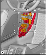
Mine have been great thus far. No issues with false positives for me at this point, knock on wood. The adhesive on the brackets is no good though (as you know if you've read through this thread). So definitely pick up some plastic bond/epoxy and use that to secure the sensor brackets, otherwise they will fall into your bumper at some point.

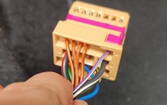
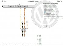
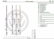
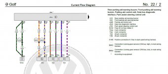
I check all my new harnesses to make sure they are wired properly and that pins are secure. I've not had anything wired incorrectly (pin > pin) yet, but always worth a check. It's also worth checking the wiring colors against the Erwin diagrams and noting any differences, especially if you're going to be re-pinning. I have had the colors be different on a few occasions. I'm an aircraft electrician by trade so this is in my wheelhouse and the quality of wiring in AliExpress harnesses is not notably different from the factory wiring in the car, imo. None of it is particularly high quality but it's sufficient for vehicle use.

At this point I've installed several harnesses from AliExpress and have yet to have an issue besides re-pinning of this harness to switch sides... Parking Aid/Assist, Blind Spot Monitoring, Dynamic Chassis Control, Auto-Dimming Mirror, Rain Light Sensor, Fog Lights, Shifter Switches, Adaptive Cruise Control, and Lane Assist Camera
 

joka23

New member
Location
UK
Car(s)
golf mk7 1.4 TSI
I am going to use this post as an update to try help anyone who is trying to do this retrofit for UK/ RHD cars.

I took apart some of the lower panels on either side of the car today with the objective of connecting the CAM wires onto the TIUL, I failed.
I do not want to try reach and unplug the gateway module as a previous post said it was really difficult.

Do not bother stripping the drivers side for RHD cars looking for this plug, as on BOTH LHD and RHD cars the connector is found on the left side of the vehicle.
You can get to it by ripping off the bottom trim and side trim (except we dont have to deal with the bonnet release which makes our life easier).
After looking at all of the connectors, it seems to be the one labelled D (have only assumed this because it is the only one with CAN cables).

I failed for two reasons:
  • The TIUL pins are different to the gateway pin size, this means you cannot just remove the pins and use the connection provided. This means I will have to splice into 2 cables (annoying but in my opinion will make my life easier)
  • The second issue can be seen if looking at the second two photos. Pin 2 and 4 are the same colour. After looking over wiring diagrams I found on Google I found the connector T17e and pins 1-4. Pins 1-2 seems to be for Powertrain CAN bus, high and low. While pins 3-4 are for running gear sensors high and low. HOWEVER, o_a_raviposted a picture of a wiring diagram (page 4) showing that B663/B664 are used for suspension sensor CAN bus? While my diagram shows B663 and B664 being used for running gear sensors (also screenshot provided).
    • I would greatly appreciate if someone can verify which pins I should be using at the TIUL, i believe someone asked in this thread but was not answered previously.
To paint the sensors I will be using Halfords Volkswagen Night Blue paint (my paint code is LH5X) as it is cheap and apparently the correct paint code. I will update on how good this paint is. As suggested on the can, I will be using grey primer. I will be using clear coat instead of lacquer as this is what I have lying around.

Tomorrow I will be trying to run the rest of the cables. Power etc, will be leaving the CAN for now. Hopefully also spray painting the sensors as british summer has finished and we are back to clouds and rain as per usual.

I have also decided I will be running the cables on the left hand side of the car. This is for a couple reasons.
  • I do not care about OEM location and seeing as someone else had trouble installing the plastic trim I will instead be using double sided tape to stick this somewhere (possibly behind the glovebox?) This should make a few things easier:
    • Can cables will be nearby
    • Same as the fuse box for GND + switch live
    • Will not have to repin cables for rear sensors.
    • I think the OEM speaker location is on the passenger side anyway (might be wrong).
  • One thing that will be more difficult is using the blue cable to reach the headlight switch location, this may need an extensions. Not the end of the world as this cable is not critical to the operation of the sensors (as stated previously).
 

Attachments

  • TIUL location.jpg
    TIUL location.jpg
    66 KB · Views: 114
  • TIUL.jpg
    TIUL.jpg
    427 KB · Views: 103
  • TIUL2.jpg
    TIUL2.jpg
    345.4 KB · Views: 105
  • Wiring_Manual_compressed.pdf
    14.3 MB · Views: 107
  • T17e pin1 and 2.jpg
    T17e pin1 and 2.jpg
    138.2 KB · Views: 102
  • T17e pin3 and 4.jpg
    T17e pin3 and 4.jpg
    183 KB · Views: 103
  • wiring diagram is different compared to o_a_ravi.jpg
    wiring diagram is different compared to o_a_ravi.jpg
    118.4 KB · Views: 114

Fraysa

Go Kart Champion
Location
Israel
Car(s)
2016 MK7 1.4TSI
Very nice progress, looking forward for me. Feel free to ask any questions as this is a big project (took me around a couple of months to finish, doing one thing at a time). If I remember correctly, the speaker for the front sensors in RHD vehicles is indeed above the glovebox compartment.
 

joka23

New member
Location
UK
Car(s)
golf mk7 1.4 TSI
Very nice progress, looking forward for me. Feel free to ask any questions as this is a big project (took me around a couple of months to finish, doing one thing at a time). If I remember correctly, the speaker for the front sensors in RHD vehicles is indeed above the glovebox compartment.
Thank you, appreciate the offer! I think so far it's just making sure I am cutting into the correct wires.
 

xabhax

Drag Racing Champion
Location
Manchester Township, New Jersey
Car(s)
15 GTI
I would suggest not using double sided tape for the sensor brackets. I had so many problems with them falling off. I ended up using 3M 2 part epoxy. Stuff no joke.
 

joka23

New member
Location
UK
Car(s)
golf mk7 1.4 TSI
You don't have to cut any wires, AFAIK.
I think this is only if you two into gateway 19. If you tap into TIUL the connectors are a different shape, therefore would need cutting (have not performed this yet, will update).

I would suggest not using double sided tape for the sensor brackets. I had so many problems with them falling off. I ended up using 3M 2 part epoxy. Stuff no joke.
I actually removed one if the red stickers and touched the glue/ tape they use. It's a joke how terrible it is. I have bought JB weld black and others suggested.
Should I remove the slight residue leftover by the tape for a clean surface or is a little residue ok?
 

IWMTom

Autocross Newbie
I think this is only if you two into gateway 19. If you tap into TIUL the connectors are a different shape, therefore would need cutting (have not performed this yet, will update).


I actually removed one if the red stickers and touched the glue/ tape they use. It's a joke how terrible it is. I have bought JB weld black and others suggested.
Should I remove the slight residue leftover by the tape for a clean surface or is a little residue ok?
Or just use a couple of scotchlocks...
 

Cuzoe

Autocross Champion
Location
Los Angeles
Should I remove the slight residue leftover by the tape for a clean surface or is a little residue ok?
I did not remove the residue, and I'm happy with the "flushness" of my sensors. I guess removing the residue might have let them be more flush, but we're talking hair widths.
 

Fraysa

Go Kart Champion
Location
Israel
Car(s)
2016 MK7 1.4TSI
I think this is only if you two into gateway 19. If you tap into TIUL the connectors are a different shape, therefore would need cutting (have not performed this yet, will update).


I actually removed one if the red stickers and touched the glue/ tape they use. It's a joke how terrible it is. I have bought JB weld black and others suggested.
Should I remove the slight residue leftover by the tape for a clean surface or is a little residue ok?

The seller I purchased from sent CAN extension adapters so you don't have to cut the original wires.

I suggest removing the residue.
 

joka23

New member
Location
UK
Car(s)
golf mk7 1.4 TSI
Or just use a couple of scotchlocks...
Ah yes sorry, this is what I meant! I did use scotchlocks for this. But I guess you do "cut" the original cable compared to using the provided extension connector.

I did not remove the residue, and I'm happy with the "flushness" of my sensors. I guess removing the residue might have let them be more flush, but we're talking hair widths.
I was more thinking about ensuring the epoxy sticks. Should be fine just overthinking.

Since my last update I have done the following:
  • Spray painted my sensors LH5X and waiting for them to dry to then apply a clear coat layer. @Fraysa I read on some other posts if you have too thick of a paint coat it can effect the sensors? Possibly why you are getting false positives? (completely hypothetical).
  • Tapped into the TIUL cables using the same method @Reaper1 mentioned here. Which is pin 3 and 4. I am RHD so it is passenger foot well.
  • Powered the unit using the fuse box behind the glove box (under steering wheel for LHD). No pictures of this as I tapped into the instrument cluster but it is not a switch live but a constant live. Will change later (hopefully will not drain my battery in the meantime).

I was hoping to do some simple coding and get the module beeping/ some sort of error like @Fraysa did previously. I cannot code the module in gateway 19 to show up/ connect and would greatly appreciate any help.
I do not have module 10 in my gateway list coding, only 76 as @Reaper1 mentioned here (they also mentioned their coding was accepted and was working fine even though it was not in gateway 10, as they also lack this gateway number). The coding is accepted but when I try click on the module it times out as no communication is found, error code "U104E00" is found in gateway which is to do with no communication.
When pressing the parking sensor button (one at the bottom) it does flash orange, just like @Fraysa showed in page 5 of his second YouTube video, no change in infotainment screen or instrument cluster (assuming this is because coding on those units has not been performed). I would have thought that I would be atleast able to interact with the unit with only the front harness connected as this provides power, and information. Without any sensors/ looms connected. I also did connect the front speaker and heard no audio.

Any advice on how to proceed with interacting with the parking module would be greatly appreciated. Thank you so much for your help so far.
 

xabhax

Drag Racing Champion
Location
Manchester Township, New Jersey
Car(s)
15 GTI
Are you using a new module, or used. 8 sensors or 12? Part number of module?
 

joka23

New member
Location
UK
Car(s)
golf mk7 1.4 TSI
Are you using a new module, or used. 8 sensors or 12? Part number of module?
I believe it is a used module as the AliExpress seller has a sticker on it which says "tested by Patrick". It is also the 12 sensor version.
I will be double checking my scotchlock connections as these are the signal cables and without this I should get the same symptoms I am currently getting (power but no communication). If that doesn't work I will be checking continuity between the CAN pins and the scotch lock
 

xabhax

Drag Racing Champion
Location
Manchester Township, New Jersey
Car(s)
15 GTI
I would get of those scotch locks, and use heat shrink and solder. Using scotch locks is asking for bad connection issues down the road. If you cannot reach the pla module its the wiring to that module.
 
Last edited:

Cuzoe

Autocross Champion
Location
Los Angeles
Or crimping, if you have (or get) the tools. Provides an easy, repeatable connection. You'll still use heat shrink (or equivalent insulating sleeve) over the connection of course... but crimping is fool proof, easy to see if it's wrong. I would choose to crimp over solder 7 days a week and I'm good at soldering. But it's too much work for no gain... hot iron and solder, potential to put too much heat into the wire and difficult to do in tight spaces.
 
Top