7
You are using an out of date browser. It may not display this or other websites correctly.
You should upgrade or use an alternative browser.
You should upgrade or use an alternative browser.
MK7.5 OEM LED Headlights Retrofit
- Thread starter AWD4416
- Start date
I make everything from your coding … but I get errors … i retrofit from 8IT to 8IUControl unit: 09 Central Electrics
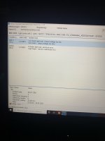
Code:Adaptations: ############################ Enable new light settigns ############################ Leuchte6ABL LC5: Lasttyp 6: 5 - LED Abblendlicht Lampendefektbitposition 6: 36 Fehlerort mittleres Byte DTC-DFCC 6: 1a Lichtfunktion A 6: Abblendlicht links Lichtfunktion B 6: Lichthupe generell Dimmwert AB 6: 127 Lichtansteuerung HD AB 6: always Lichtfunktion C 6: nicht aktiv Lichtfunktion D 6: nicht aktiv Dimmwert CD 6: 0 Dimming Direction CD 6: maximize Lichtfunktion E 6: nicht aktiv Lichtfunktion F 6: nicht aktiv Dimmwert EF 6: 0 Dimming Direction EF 6: maximize Lichtfunktion G 6: nicht aktiv Lichtfunktion H 6: nicht aktiv Dimmwert GH 6: 0 Dimming Direction GH 6: maximize Leuchte7ABL RB1: Lasttyp 7: 5 - LED Abblendlicht Lampendefektbitposition 7: 40 Fehlerort mittleres Byte DTC-DFCC 7: 1b Lichtfunktion A 7: Abblendlicht rechts Lichtfunktion B 7: Lichthupe generell Dimmwert AB 7: 127 Lichtansteuerung HD AB 7: always Lichtfunktion C 7: nicht aktiv Lichtfunktion D 7: nicht aktiv Dimmwert CD 7: 0 Dimming Direction CD 7: maximize Lichtfunktion E 7: nicht aktiv Lichtfunktion F 7: nicht aktiv Dimmwert EF 7: 0 Dimming Direction EF 7: maximize Lichtfunktion G 7: nicht aktiv Lichtfunktion H 7: nicht aktiv Dimmwert GH 7: 0 Dimming Direction GH 7: maximize Leuchte8FL LB39: Lasttyp 8: 5 - LED Abblendlicht Lampendefektbitposition 8: 44 Fehlerort mittleres Byte DTC-DFCC 8: 4b Lichtfunktion A 8: Versorgungsbedarf der LCM Module Lichtfunktion B 8: nicht aktiv Dimmwert AB 8: 127 Lichtansteuerung HD AB 8: always Lichtfunktion C 8: Standlicht allgemein (Schlusslicht, Positionslicht, Begrenzungslicht) Lichtfunktion D 8: Parklicht rechts Dimmwert CD 8: 127 Dimming Direction CD 8: maximize Lichtfunktion E 8: nicht aktiv Lichtfunktion F 8: nicht aktiv Dimmwert EF 8: 0 Dimming Direction EF 8: maximize Lichtfunktion G 8: nicht aktiv Lichtfunktion H 8: nicht aktiv Dimmwert GH 8: 0 Dimming Direction GH 8: maximize Leuchte9FL RB2: Lasttyp 9: 5 - LED Abblendlicht Lampendefektbitposition 9: 3a Fehlerort mittleres Byte DTC-DFCC 9: 49 Lichtfunktion A 9: Versorgungsbedarf der LCM Module Lichtfunktion B 9: nicht aktiv Dimmwert AB 9: 127 Lichtansteuerung HD AB 9: always Lichtfunktion C 9: Standlicht allgemein (Schlusslicht, Positionslicht, Begrenzungslicht) Lichtfunktion D 9: Parklicht links (beidseitiges Parklicht aktiviert li & re) Dimmwert CD 9: 127 Dimming Direction CD 9: maximize Lichtfunktion E 9: nicht aktiv Lichtfunktion F 9: nicht aktiv Dimmwert EF 9: 0 Dimming Direction EF 9: maximize Lichtfunktion G 9: nicht aktiv Lichtfunktion H 9: nicht aktiv Dimmwert GH 9: 0 Dimming Direction GH 9: maximize ************************* Optional disable foglights as cornering lights ************************* Leuchte12NL LB45: Lichtfunktion B 12: nicht aktiv Leuchte13NL RB5: Lichtfunktion B 13: nicht aktiv ******** Enable AFS settings on the car settigns menu ********* Fernlicht_assistent: Erweiterte_Fernlichtsteuerung: AFS, FLA, Fernlicht ueber AFS (for hight beam assist with module A5) AFS, Fernlicht ueber AFS (if you do not have module A5) Menuesteuerung Fernlichtassistent: Present Fernlichtassistent Reset: active ************************************* Enable Level Adjust Sensor non-DCC ************************************* Leuchtweitenregulierung: sensor_headlight_range_control_installed: rear sLWR_verbaut: not installed 1_Sensor_LWR: 1-Sensor_LWR Fahrwerk_Variante: Variante_1 sLWR_bei_Abblendlicht: active Quelle_Hoehenwerte: BCM ************************************* Enable 4B to control lights ************************************* Aussenlicht_uebergreifend: Light_Control_Module: installed LCM_blinker: FALSE ************************************* Not 100% possitive this is needed ************************************* Aussenlicht_Blinker: dynamisch_blinken_10: active
Control unit: A5 Driver Assistance
Code:Long coding FLA_Headlight_type LED FLA_Additional_High_Beam no_Additional_High_Beam AFS_coding_Light_Assist High_Beam_Assist
On the radio under Vehicle settings
Code:Light settings Light Assist Turn-on time: Early
Attachments
-
 09460255-6942-4A87-98F4-E26CD260DF9B.jpeg1.6 MB · Views: 331
Please verify the connections on the 14 Pin connector. I just update some of that information.I make everything from your coding … but I get errors … i retrofit from 8IT to 8IU
Ok thank you … I resolve the problem … it was not correct xml files on my 4B module … in my 8IT was without dla and now my headlights is 8IU and was need xmlPlease verify the connections on the 14 Pin connector. I just update some of that information.
Carolco
Passed Driver's Ed
- Location
- Islas Canarias
Ok, gracias ... resuelvo el problema ... no eran archivos xml correctos en mi módulo 4B ... en mi 8IT estaba sin dla y ahora mis faros son 8IU y necesita
What xml files did you used? What model unit 4B do you have?Ok, gracias ... resuelvo el problema ... no eran archivos xml correctos en mi módulo 4B ... en mi 8IT estaba sin dla y ahora mis faros son 8IU y necesitaba xml
As headlights are used they was have correct xml the problem was with the 4B xml my 4b doesn’t have dla … my 4b is just without letter in the endWhat xml files did you used? What model unit 4B do you have?
can you share the XML file you used please and the reference of your 4B module, thank youAs headlights are used they was have correct xml the problem was with the 4B xml my 4b doesn’t have dla … my 4b is just without letter in the end
such as errors caused by hardware, not coding.I make everything from your coding … but I get errors … i retrofit from 8IT to 8IU
In my way I retrofit the 8IT to 8IU and after coding the problem is the xml on 4B modulesuch as errors caused by hardware, not coding.
Hi !!!!, Ive been working on designing custom 3d parts for the MK7-7.5 series and printing the prototipes to test and make molds for production, its been a slow and expensive process, i have a 3d scanned golf tsi just like mine but its not high res, so theres a lot of try and error in the fittings, wich means going back to 3d, adapt and print again. those images on you coment, the CAD ones, it would be the best thing if I can get that CAD model !, with that I can make the parts perfectly from the begining and also the interior and custom engine parts !!!!, where did you got them ?At this point I’m really hopping you are committed. This is the point of no return and it will take some time to put the GTI (or whatever type of V-Dub you have) together again. This is the point where I lost my mind due to not knowing what I do now about this retrofit. It will take at least a day if doing it by yourself so plan accordingly.
The high level overview is: remove the battery, run wire harness, re-pin the new 14-pin connector, verify wire with multi meter, and the install headlights. I’ll put the connection info on the 4B installation post.
The first thing to do is remove the battery.
Remove the rubber strip from the plenum chamber cover. Then remove the two clips (3) holding the left side. Pull straight up on the cover to remove it from retainer (5).

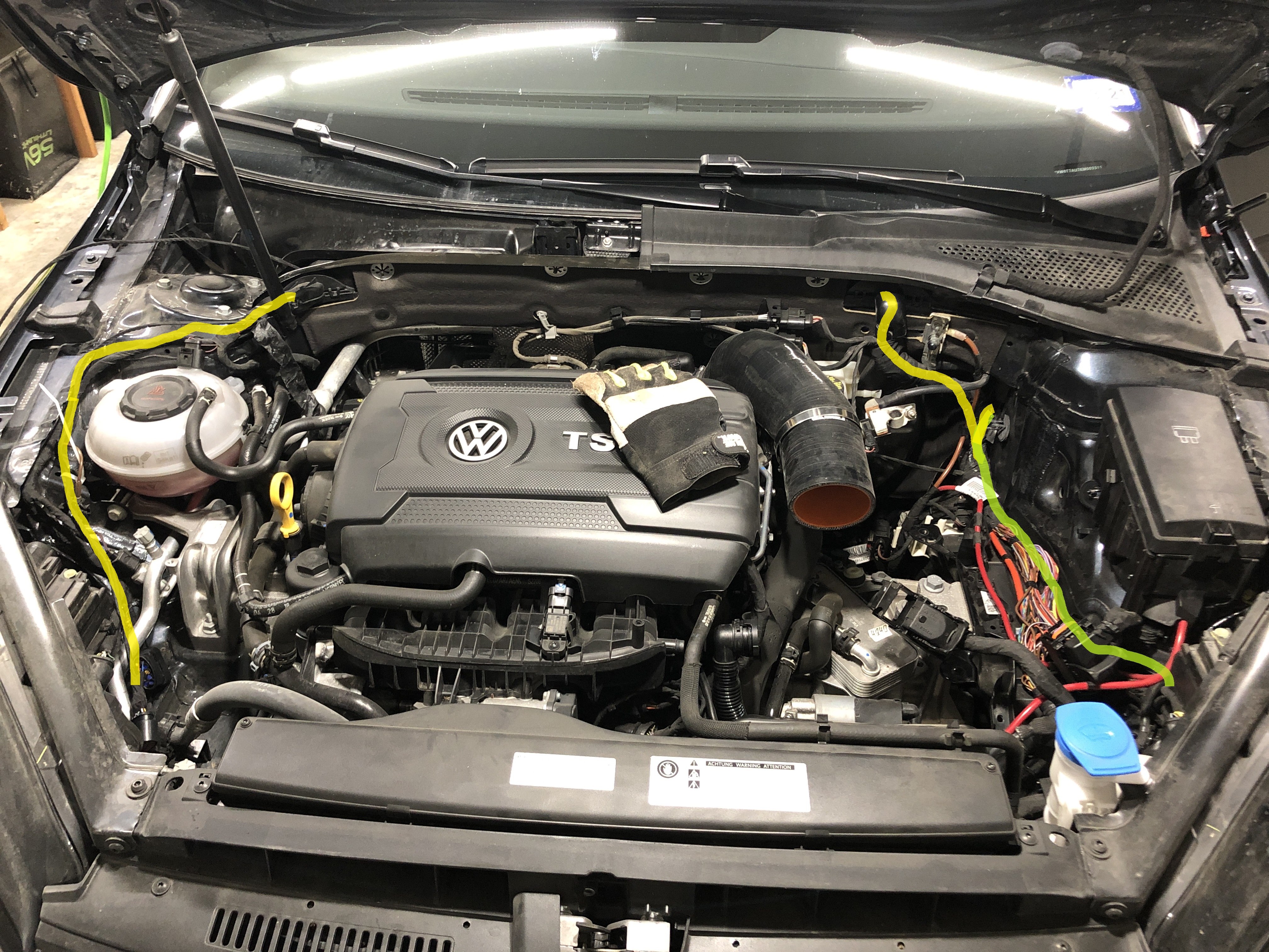
Run the right headlight hardness following the yellow path. Run the left headlight hardness following the green path.
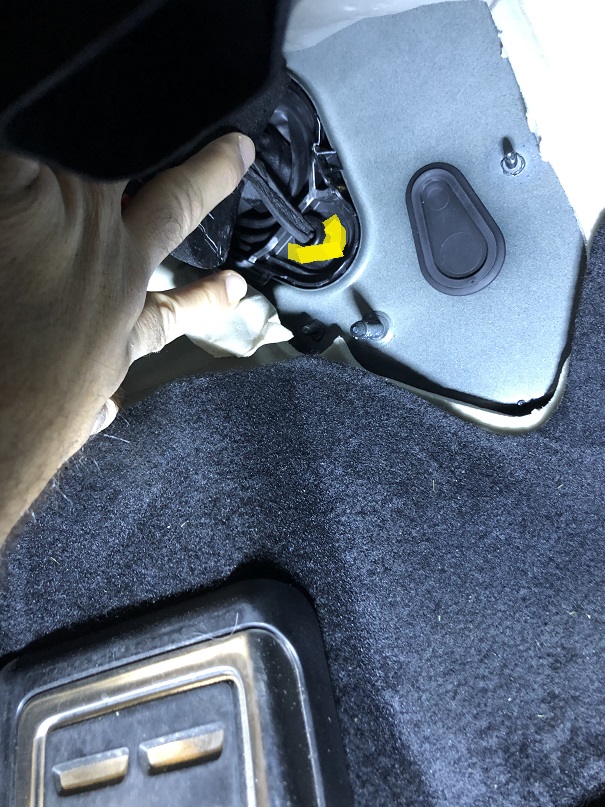
From the inside of the cabin, puncture a hole on the yellow part of this grommet to run the wire harness inside. I found a wire cloths hanger super helpful in this step.
Re-Pin the original 10 pin Halogen lights connector to the 14 pin LED lights connector. For the wires that are not used, cut them and put black tape or a shrink wrap sleeve on the tips. Then wrap them around the harness. Use some tape to wrap them to the harness. I cut and solder some of the wires since some of the pins in the 14 pin connector are smaller than the 10 pin connector. This is why checking the wires with the multi meter is extremely important. When putting the pins in the connector, try to reuse the rubber gasket to stop humidity/water from getting to the terminals.
Left 10-Pin connector Wire Color 14-Pin connector Wire Color Function BCM connection 4B connection Note 1 Orange/Gray CAN-H 15 2 Orange/Brown CAN-L 5 4 12v Splice to 8 , 8IU only5 Brown GND Use the ground by the driver side door 6 Yellow 6 Yellow Signal 73c/5 7 GND Splice to 5, 8IU only8 Black/Lilac 12v New Fuse 37 8 White/Black 11 Blue/White Signal 46b/39 1 Black/White 13 Gray/Black Signal 73a/72 USA - only
Right 10-Pin connector Wire Color 14-Pin connector Wire Color Function BCM connection 4B connection Note 1 Orange/Gray CAN-H 15 2 Orange/Brown CAN-L 5 4 12v Splice to 8, 8IU only5 Brown GND Use the ground by the driver side door 6 Yellow/Blue 6 Yellow/Blue Signal 46b/1 7 GND Splice to 5, 8IU only8 Gray/Black 12v New Fuse 36 8 White/Purple 11 Blue/White Signal 46b/2 1 Gray/Black 13 Gray/Black Signal 73a/72??? USA - only
Wiring diagram
View attachment 223113
Before removing the headlights, use tape to outline how they fit on the bumper. This helps in making the new headlights flushed.

Remove the two screws holding the grill in and pull the grill off. Point to think about, this will remove the radar from the car. However, since no real change has been made to the cars dimension, it should still be within specs after re-installation. Remove the radar plug.
*Since completing this guide, I have retrofitted the front assist camera. I can confirm that if the radar is removed while the battery is disconnected, there should be no issues with the radar if re-installed properly.

Remove the screws inside the wheel well.
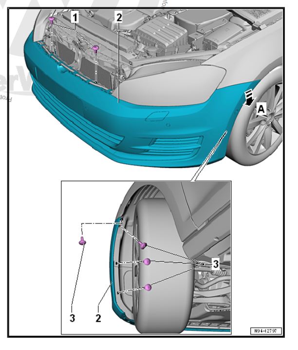
Remove the screw behind the bumper holding the light.
Remove the bolts holding the headlight in place to include the metal bar.
I remember some screw/bolts I loosen up after removing the grill that allow me to pull on the bumper more so I can slide the headlights out.

Finally install the new lights and reverse the process to put everything back in place.
Thanks !
AlexRok
Ready to race!
- Location
- Eastern Canada
This is near exactly what I want to do. I have the aliexpress lights, but I'd like genuine ones.Retrofit or just looking to upgrade the headlight? Easiest way is to just toss in an Helix/BEC/Osram or other aftermarket headlight that will connect to the 10 pin harness. The lights will be static, but you'll have dynamic turns and DRLs along with LED lights.
Retrofit it depends on if you're willing to make your own harnesses. Otherwise you're looking at something like this for the 7/7.5:
You'll need wiring, perhaps a new CAN Gateway and BCM depend on your current versions and pins. If those are good you'll need the headlight AFS module, headlights and their modules, perhaps a rear level sensor, and the new wiring between the BCM, CAN, AFS Module and headlights.
Doing a partial retrofit on my MK7 with Osrams and the VW Euro low line AFS module for auto leveling.
I don't care about having any dynamic features, so I'm a bit confused by your above statement and would appreciate any help. Would I still need level sensors and wiring going to the rear of the car if I do not want any dynamic features? I just want OEM static LED replacements for my car that came halogen.
If I buy the headlight modules, and I am willing to make a harness, can I get away without swapping the CAN gateway or BCM?
StorableComa
Autocross Champion
- Location
- SoCal, USA
- Car(s)
- 17 GSW S FWD
Oem would be a xenon retrofit. I don't believe we have NAR led headlights.This is near exactly what I want to do. I have the aliexpress lights, but I'd like genuine ones.
I don't care about having any dynamic features, so I'm a bit confused by your above statement and would appreciate any help. Would I still need level sensors and wiring going to the rear of the car if I do not want any dynamic features? I just want OEM static LED replacements for my car that came halogen.
If I buy the headlight modules, and I am willing to make a harness, can I get away without swapping the CAN gateway or BCM?
For LED you'd want a aftermarket light BECs or other. They are made to replace halogen lights and be plug and play.