Luiz Henrique
Ready to race!
- Location
- Brazil
- Car(s)
- GTI
Good afternoon, I did all the tests, and I believe it is due to the firmware, but it doesn't prevent the system from working perfectly, mine is working perfect.
Good morning from Brazil @Andrew, observing your situation, I believe you will have success doing what I did in my GTI.Hi All,
I've been thinking of doing the lane assist retrofit for a while now, and my GF decided to surprise me at xmas with most of the parts needed to start the retrofit (along with the approval to actually do it, the most important part) So I've spent boxing day and today starting to wire it in... I am going to go the full windscreen replacement route so will need to wait till the glazier in the new year to get it fully working... (Fitting the MK7.5 windscreen with the 3Q0 Camera)
However come across two things so far with the wiring which I am not sure about, I managed to get the loom (came with the pack from aliexpress) down from the roof console behind the fusebox (two wires for the ACC through the firewall and under the battery for the moment, till my high temp tesa tape arrives)
But the two CANBUS Ext wires and the black/green wire to the fuse box (Fuse SC32) I am having trouble with...
I was going to plug directly into the CAN Gateway but my car is RHD and the loom I have is too short to easily reach the Gateway on the Right hand side of the car, so I am looking at the TIUL connector by the door, but its pins are different, and I would prefer to install without cutting any factory wires.
Any suggestions on how to do it?
Currently I am leaning towards extending the canbus wires across to the gateway and a gateway canbus ext splitter https://www.aliexpress.com/item/4001005833337.html?spm=a2g0o.cart.0.0.1eb93c00rX4gkn&mp=1
or getting some new pins for the TIUL connector and re crimp the lane assist loom with the same connectors as the TIUL plug/socket and use a couple of the unpopulated spots in the plug to do the y split so I don't have to cut the existing wires...
or am I missing a simple way of doing it?
The second problem I have is power connector, I already have blindspot/acc etc populating SC32, what have people been doing to connect this wire?
I noticed playing with the TIUL connector that the same power wire for the ACC which goes to SC32 goes through there, but I am not sure what the terminal type is, I don't currently have the right depinning tool to get it out to check.. does anyone know? (T17l/15, T17d/15)
Cheers
Andrew
Cool, Thanks Luiz, well I guess the question I best need answered is does anyone know what is the connector type for Pin 15 on the TIUL connectors?Good morning from Brazil @Andrew, observing your situation, I believe you will have success doing what I did in my GTI.
1- You can buy the Canbus extender and it will be the best of all worlds, but in my situation I didn't have the extender at the time, so I used points 13 (Can bus Extended low) and 12 (Can bus Extended high) from TIUL (T17K ) (black plug).
2 - 12V power supply from the camera to be connected to point 15 of the T17K connector on TIUL.
 )
)I didn't have to go to that point, I thought it would be a waste of time to look for the connector to do this, so I provided a branch splice, and applied a thermo-contracting blanket! It was perfect. in 5 minutes everything was resolved!!!!Cool, Thanks Luiz, well I guess the question I best need answered is does anyone know what is the connector type for Pin 15 on the TIUL connectors?
Pins 1-14 seem to be 000979034E and 000979035E (male and female) but pins 15-17 seem to be different and I can't find any reference to what terminal type they are... and I can't extract the current one to compare as I don't have my extractor tools yet (my little pick I used to get the other pins our doesn't fit


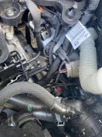
I did the Installation of cables on the ACC Radar and found no difficulty! Ebcaninei the pair of cables by the side passing through the battery and reaching below the left headlamp! abs.So Xmas/News Years is slowing everything down as parts ordered at Xmas are only just shipping
I ordered a bunch of mcon 1.2 LL & amp mcp 2.8 crimp terminals and connector housings so I can connect the CAN wires and the wire which is supposed to go to Fuse S32 to TIUL connector without cutting/splicing the factory loom.
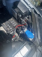
my high temp tesa tape did arrive this morning, so I've wrapped the can bus wires that I pushed through the firewall and routed it under the battery in the wire routing box thing.
View attachment 234544
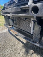
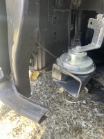
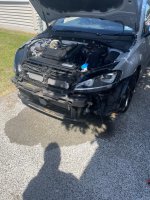
I am just not sure where to go from here, do I need to remove the bumper to route down to the ACC Radar or If people have been successful at routing the wires without removing it? and if so where/how did you route the wires?
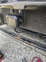
Decided to take the bumper offI did the Installation of cables on the ACC Radar and found no difficulty! Ebcaninei the pair of cables by the side passing through the battery and reaching below the left headlamp! abs.

Just posting some photo ref since there isn't a lot out there for routing the cables...Decided to take the bumper off
Not as scary as I first thought

perfect, that's it!Decided to take the bumper off
Not as scary as I first thought

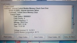
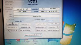
Good evening everyone, I'm stopping by to share the experience, in solving a problem that occurred in the FLA system. finally everything is working perfect and calibrated. It all started when I was doing the Dynamic calibration of Camera 5Q0, there was a failure and I had to go back home and see what had happened, I found that the static calibration was not done well, well, in the meantime doing some tests, I noticed that the automatic switching of the headlamp (FLA) was showing a failure in the panel and in the multimedia, with the VCDS I identified that the problem was in the voltage regulator circuit of the board in the Fotochromico internal rearview mirror (3G0857 511 AE). I tried everything to (revive the board), but without success! But even with this problem on the board, the power supply part of the photochromic mirror continued to function normally, only the headlamp switching circuit was in fault. So I went in search of another infinity edge mirror, and I found one that served me well (3G0857 511 AC), since this one doesn't have circuit for automatic switching, function is done by camera 5Q0, however! there's always a but hahaha! the connector (3G0857 511 AC) only had 4 wires, and without the CAN network, something different from the problem model, which had 7 wires with the CAN network too, so I had to make an adaptation to the plug to make it work perfectly . Another problem I found was on the 5Q0 camera, which unlike the 3Q0, when used with a rearview mirror (AC), must code as LA and not FLA, even if a car has this factory system! In the case of the 3Q0 camera, the encoding must be set with FLA. Anyway, everything works as it has to be.Good afternoon everyone, today a curious situation happened! I went to test the headlamp with automatic switching, and noticed that it was giving an error on the panel stating a failure in the assist light, I found it strange as it was using the lane assist camera on the 5G0! When I got home I checked with the VCDS and it was failing module 20, indicating problem in the module, so I did the module flash update to see if it came back, but to my sadness, nothing!!! So I looked for another mirror I have, to take the license plate and test it, but this plate is from a car that already came from the factory with lane assist, that is without the camera in the rearview mirror, I noticed that the wiring is not the same (only the power cables ). I had some doubts: as I was using an internal rearview mirror of a tiguan in my golf, I disconnected the rearview camera, because I installed the lane assist camera 5G0, following this rationale, I thought erm install the rearview that came from the factory without the camera, just to use the anti-glare system, but it didn't work! how do I disable module 20 so that the system does not find the module, that way I would be using the 5G0 camera as well as an automatic headlight system.


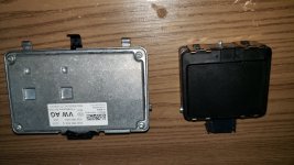
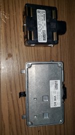
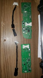
Extensions are a must for retrofits. either you will make your own cables, or you will buy ready-made cables and extend themView attachment 235248View attachment 235247View attachment 235246
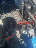
Quick update on my setup of not cutting into the loom, my crimp terminals and connectors turned up this weekend, I had to make a shot extension of the power line to the camera as it ended up been 20cm too short (seen here prior to the connectors arriving. I also re crimped the cam lines from the camera with the TE micro 1.2 crimps, and used an appropriate connector type so I just had to de pin the body connector wires and plug them into the new connector.
the connectors were a touch bulkier then I expected, but they fitted in well enough.
Tomorrows job is heading to the dealership to the have the Active display instrument cluster installed (they just have to code it in) and maybe also get the windscreen done if they allow it (sacrilege in this thread)
")