Hey Guys!
I've been lurking on this form for a week or so, and I wasn't able to find the info I needed to install a backup camera on my 2015 Golf S (US Model). I eventually found the info I needed from a kind eBay seller, so I thought I'd share it with you.
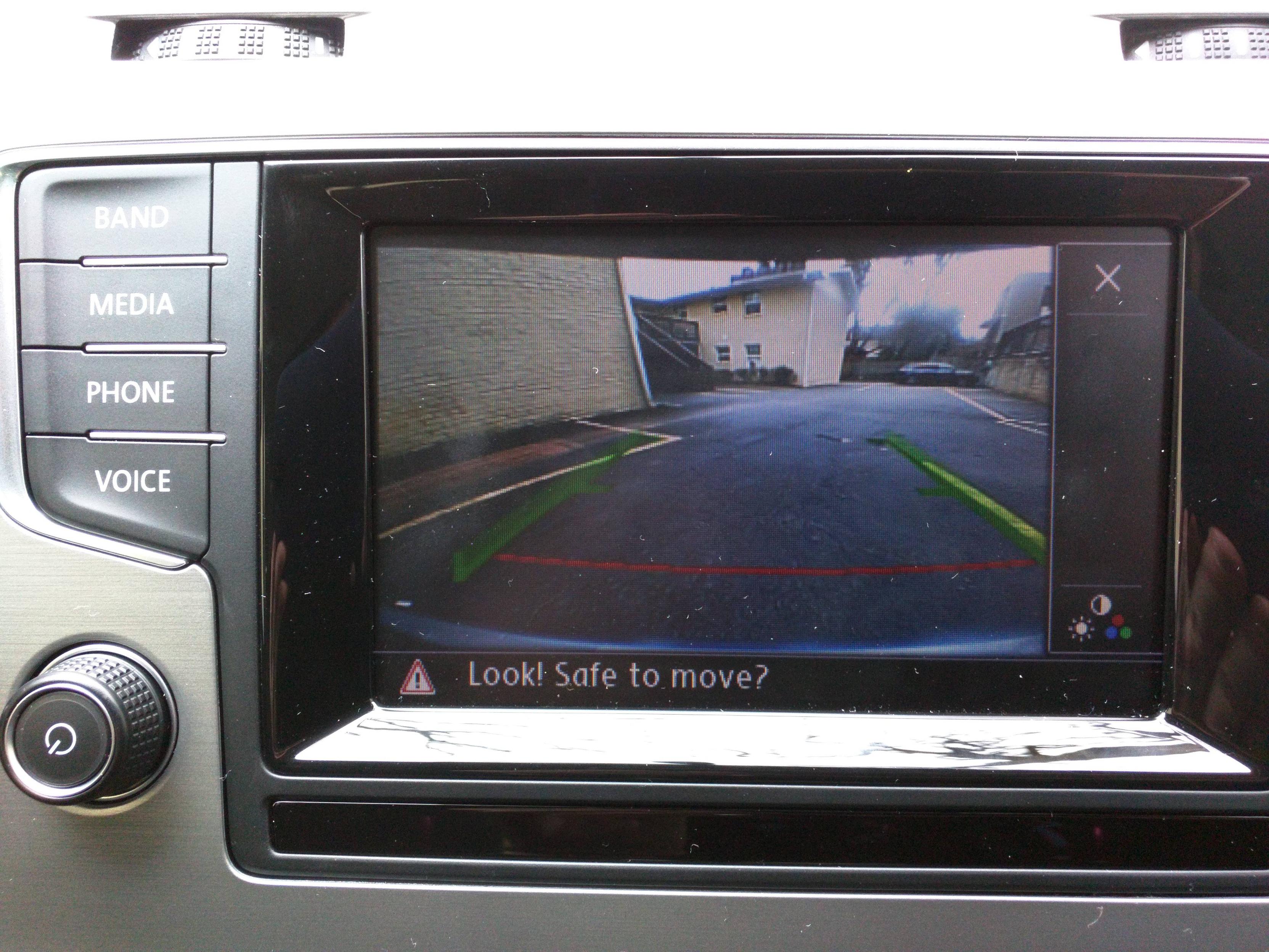
The actual camera install and wiring is pretty straight forward. I just started ripping panels off and I was able to get access to the rear emblem/hatch handle. I tapped into the reverse bulb wire on the passenger side of the vehicle to get a positive reverse signal.
I ran the cable through the interior panels before arriving behind the glove box. From there, I stole power from the red wire leading to the radio harness. The two wires (and attached pins) plug into spot numbers 6 and 12 on the blue harness behind the glove box radio module.
After the wiring is in place, some VCDS coding needs to be changed.
1. Using the VCDS diagnostic device, open the box 5F - Information Electr.
2. Now locate Byte no. 19
3. Mark then bit no. 4
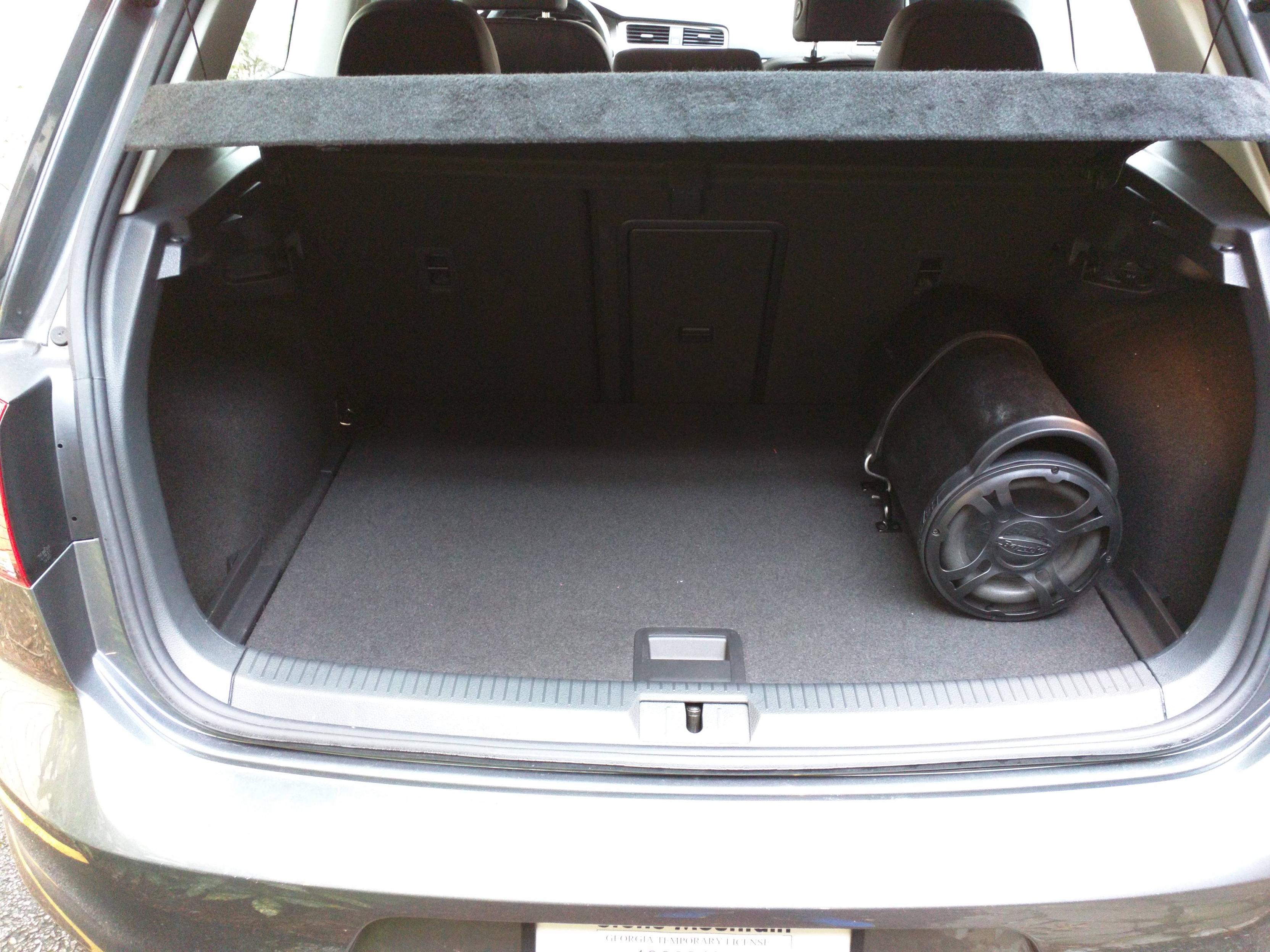
That's all. My installation took a lot longer than I wanted it to, but I was also running wiring for a sub woofer at the same time. That added some unexpected challenges that I won't go into right now.
This is the camera I bought - It's from an Australian eBay seller, and the exchange rate worked in my favor.
I did not take photos of the install process, and I apologize for that. I was way too excited to install it, I forgot to take any pictures.


I've been lurking on this form for a week or so, and I wasn't able to find the info I needed to install a backup camera on my 2015 Golf S (US Model). I eventually found the info I needed from a kind eBay seller, so I thought I'd share it with you.
The actual camera install and wiring is pretty straight forward. I just started ripping panels off and I was able to get access to the rear emblem/hatch handle. I tapped into the reverse bulb wire on the passenger side of the vehicle to get a positive reverse signal.
I ran the cable through the interior panels before arriving behind the glove box. From there, I stole power from the red wire leading to the radio harness. The two wires (and attached pins) plug into spot numbers 6 and 12 on the blue harness behind the glove box radio module.
After the wiring is in place, some VCDS coding needs to be changed.
1. Using the VCDS diagnostic device, open the box 5F - Information Electr.
2. Now locate Byte no. 19
3. Mark then bit no. 4
That's all. My installation took a lot longer than I wanted it to, but I was also running wiring for a sub woofer at the same time. That added some unexpected challenges that I won't go into right now.
This is the camera I bought - It's from an Australian eBay seller, and the exchange rate worked in my favor.
I did not take photos of the install process, and I apologize for that. I was way too excited to install it, I forgot to take any pictures.