GOLFMK8
GOLFMK7
GOLFMK6
GOLFMKV

PDC Retrofit Question

Cuzoe

Autocross Champion
Location
Los Angeles
We know, Ali is no good for you, haha. All genuine or nothing at all. Why is genuine in caps? I think you're just hard on harnesses 😂.

Post a picture of the weird weld though. My harness works fine, but I'd like to see what's in there, haha.
 

Fraysa

Go Kart Champion
Location
Israel
Car(s)
2016 MK7 1.4TSI
We know, Ali is no good for you, haha. All genuine or nothing at all. Why is genuine in caps? I think you're just hard on harnesses 😂.

Post a picture of the weird weld though. My harness works fine, but I'd like to see what's in there, haha.
F7341F4B-076A-410E-902F-701D4498D70C.jpeg


I wouldn’t call it a “weird weld”, but instead of going in a “tree” pattern (giving each sensor their ground on the way, instead the main ground wire splits in the center and all of them join in one spot, using a cheap shrink. Slicing through the adhesive around the loom was also a huge challenge, they used the cheapest kind of glue.
 

Attachments

  • A3BB81D3-31B4-43B9-84F5-A1341445D5AC.jpeg
    A3BB81D3-31B4-43B9-84F5-A1341445D5AC.jpeg
    1.9 MB · Views: 80

Cuzoe

Autocross Champion
Location
Los Angeles
Oh, all the grounds at one splice point. That is the way we would do it on aircraft. Wire is cheaper than splices. And every splice is a potential failure point. The downside of course, if your one splice isn't good you have multiple problems.

Somewhat related, the reason we don't (as a general practice) weld wires together is to avoid problems like this. Weld points can be brittle, you can fail to flow the solder properly, you can wick solder into the wire (inside of the insulation) making the wire brittle, etc. A solid mechanical splice is much less risky. Plus you can see if you screwed it up right away.

I agree that stripping these harnesses sucks. Having stripped into the factory harnesses in my car at the gateway, BCM, ABS, door disconnect, etc. It's the same sh!t, All of it is terrible. The heat makes it sticky and some of them are a double wrapped with the tape going in both directions so you can't just un-wrap it. If you are stripping harnesses you are having a bad time.
 
Last edited:

Fraysa

Go Kart Champion
Location
Israel
Car(s)
2016 MK7 1.4TSI
78D4DB66-D7B7-4D09-82CA-9A4A48E128E1.png

I found an eBay listing for a genuine wiring loom for the 6 sensors. However this one has also 2 extra connectors for the license plate lights. I assume it will work with my current setup (the connector looks to be the same 8 pin connector as the PDC one, I assume it just steals 12V and ground for the license plate lights to make one loom$.

However I’ll be left with the original factory loom for the license plate lights connected to nothing.

Any insights on this move?
 

Luiz Henrique

Ready to race!
Location
Brazil
Car(s)
GTI
boa noite, desde que fiz o retrofit do park assist 2.0 para 3.0 no meu golf gti 2015, estou recebendo uma mensagem na tela do painel: "freio de manobra não disponível". Estou com o módulo Park Assist 3.0, 5QA919298F
Boa tarde do Brasil a todos, passando pela caixa de entrada e minhas interações no grupo, percebi que havia uma dúvida nesse tópico, sem uma resposta minha, bom, vamos lá! Tive alguns problemas com meu sistema de park assist, a princípio meu carro não vinha de fábrica com park assist 2.0 (módulo 5Q0919298k), então comprei todo o material no aliexpress, instalei e configurei via vcds, até que ok, mas Achei o sistema um pouco instável ao estacionar (salve essa informação !!), mas tudo bem! Eis que atualizei o sistema para park assist 3.0, e para isso troquei o módulo, por um 5QA919298F, fiz a configuração do vcds e funcionou, mas com um problema novo, sempre apareceu no painel de instrumentos a mensagem "Freio de manobra não disponível ", verifiquei toda a configuração e nada! então em algumas pesquisas em um site russo, percebi que poderia haver um problema no arquivo flash, e / ou na parametrização, então fiz downgrade do módulo para a versão C e carreguei os novos parâmetros, bom, esse problema foi resolvido, entretanto! kkkk, o problema de instabilidade no estacionamento persistia, então me veio a ideia de testar sensor por sensor, e notei algo estranho os sensores traseiros estavam invertidos, porém a instalação foi seguida conforme o guia, mas aí veio o problema real! quando comprei todo o material, esse veio da china (aliexpress), a fiação traseira estava invertida! A mudança foi feita e testada, o sistema funcionou perfeitamente, sem oscilações que existiam ao estacionar. Graças a Deus!
 
Last edited:

Fraysa

Go Kart Champion
Location
Israel
Car(s)
2016 MK7 1.4TSI
I found an eBay listing for a genuine wiring loom for the 6 sensors. However this one has also 2 extra connectors for the license plate lights. I assume it will work with my current setup (the connector looks to be the same 8 pin connector as the PDC one, I assume it just steals 12V and ground for the license plate lights to make one loom$.

However I’ll be left with the original factory loom for the license plate lights connected to nothing.

Any insights on this move?

In addition to this, I'll also be replacing the Chinese aftermarket sensors for genuine ones. Found a guy on eBay that sells sets of genuine sensors, however the P/N for the side park assist sensors is different : https://www.ebay.com/itm/254231176992

I know from ETKA that all 6 should be the same P/N - 5Q0919275B, however this guys sells 4 of 275B and 2 with 297B.

Any idea?
 

Fraysa

Go Kart Champion
Location
Israel
Car(s)
2016 MK7 1.4TSI
The ones that came with the kit from AliExpress, which I’m sure are doing a far worse job than genuine sensors.
 

Cuzoe

Autocross Champion
Location
Los Angeles
Oh yes, I tend to forget that none of us with kits from Ali have properly working sensors. And you've done the side by side tests to be sure they are doing a worse job 😁.
 

Fraysa

Go Kart Champion
Location
Israel
Car(s)
2016 MK7 1.4TSI
well, I know how genuine sensors work because I had them on my Audi before and they’re much more accurate than what I currently have.
 

Cuzoe

Autocross Champion
Location
Los Angeles
I would check the diagrams and try to verify it's the same plug. I wouldn't think it's just tapping 12V for the lights because it's possible to get an error for the license plate bulbs being out.

That suggests the license plate lights are directly controlled by the BCM. That would make sense (to me) because the lights aren't on all the time.

I will find the wiring in the diagrams later today to verify. I've seen VW combine harnesses, which makes sense for those with the same general route (like that ebay one, or fogs/pdc/radar up front) but I would think the connectors would still be broken out.

The wiring diagrams show the systems separately but I suppose VW could combine connectors too. My Golf S came with nothing so I haven't seen any combined harnesses personally.
 

Cuzoe

Autocross Champion
Location
Los Angeles
The factory rear bumper harness for cars with PDC does include the license plate light plugs, as seen in that listing. It's a 10 pin plug (8 for PDC and 2 for plate lights, probably). Of course, your car did not come with that harness, so the wiring in your car will not properly connect to it.

If I were in your shoes I would adapt the used OEM harness to match the Ali Express harness you installed on the car side. Cut the end off of the Ali-Express bumper harness (leaving a pig-tail) and do the same with your OEM bumper harness (leaving a pig-tail). You will then switch these pig-tails, so that your OEM harness has the connector from your Ali-Express harness. You will need to verify wiring, pin by pin, when switching the pigtails.

On the OEM harness just bag the license plate light connectors. Leave your existing license plate light wiring as-is. The license plate wiring is not tapped from the power going to the sensors (which comes from the PDC module, and may not actually be 12V). License plate light wiring comes from the BCM, Plug A pin 59. In the drawings the lights are X4 and X5.

I also attached the full rear sensor diagrams, should you decide to go through with buying another harness and switching pigtails.
 

Attachments

  • License Plate 1.JPG
    License Plate 1.JPG
    133.1 KB · Views: 78
  • License Plate 2.JPG
    License Plate 2.JPG
    18.4 KB · Views: 76
  • Rear Sensors 2.JPG
    Rear Sensors 2.JPG
    104.1 KB · Views: 75
  • Rear Sensors.JPG
    Rear Sensors.JPG
    121.2 KB · Views: 76

Fraysa

Go Kart Champion
Location
Israel
Car(s)
2016 MK7 1.4TSI
Thank you for this.

I ordered the genuine harness, as well as 6 genuine sensors and brackets. This cost me around 140$ in total, but I believe it’ll be worth it to do it once and make it perfect this time!

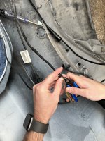
I plan to sand the inside of the bumper where the old glue used to be and make it as flush as possible as well as sand the hole the increase it by a bit (those extra 0.2mm).

I’ll go with your suggestion of using the pig tail route. Do you mind saying which pins to connect from the genuine harness to the Ali one? I’m really bad at reading those schematics.

I’ll post updates very soon!

EDIT:
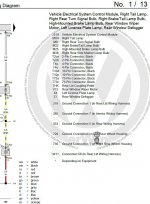
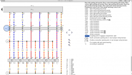
Okay, after looking at the diagrams, it seems the connections for the 10 pin connector are like so (similar to what you posted on page 21):

Sensor LocationPin No.
Right Parallel10
Left Parallel9
Power8
Ground7
Left Rear6
Left Rear Center5
Right Rear Center4
Right rear3

Consdiring the diagram you posted is for the 10 pin connector (which is also for license plates), then I assume pin 1/2 are for the license plate lights. My current harness has 8 pins (6 sensors + power/ground), and the new one is 10 pins.

Do you perhaps have a diagram for the 8 pin connector so I can see what to switch?

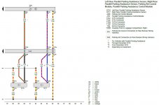
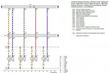
EDIT 2: Okay, I bought a 1 hour access to erWIN Online and found this:

1641119660075.png


So everything matches the table, besides pin 1/2 which are missing.

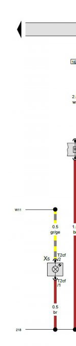
EDIT 3: Okay, some more digging... the coupling point in the boot for the license plate lights is as follows:

1641120153230.png


We can see there are two options - either a 2-pin connector (T2ca), which is what I have (and most of you guys too), or the 10-pin connector (T10la), and we can also see in the diagram below that it goes to pin 1/2 in the T10la connector:

1641120289414.png


So... mystery solved, I guess! Now I just have to find the diagram for the 8 pin connector to see which ones I'll have to replace.

My guess is that the pin numbers are just -2 for the 8-pin connector... Another route I'm thinking is possible, is to take the 2 pins from the coupling point (T2ca) and insert them into the genuine 10 pin connector. It should in theory work?

@Cuzoe WDYT about my other route? Also, are you proud of my diagnostics? :p
 

Attachments

  • 1641119618791.png
    1641119618791.png
    131 KB · Views: 71
Last edited:
Top