7
You are using an out of date browser. It may not display this or other websites correctly.
You should upgrade or use an alternative browser.
You should upgrade or use an alternative browser.
PDC Retrofit Question
- Thread starter Fraysa
- Start date
Nuje
Go Kart Champion
- Location
- Island near Vancouver
- Car(s)
- 2015 Sportwagen TDI
pm'd
Apart from from the can hi/lo connector., the other 2 extra wires are your power and ground. It one with big clip goes behind the fuse box for switched positive connection. I clipped it out and added it to an existing fuse using an add a fuse adapter.
Will post the complete wiring diagram shortly.
Attached is the wiring diagram., per the diagram your black/green wire will be positive (going to the fuse, switched positive)., grey wire on the center console switch connector goes to BCM for background illumination (Pin 73 on plug C)., this iluminates the switches white when the headlight is turned on.
Apart from from the can hi/lo connector., the other 2 extra wires are your power and ground. It one with big clip goes behind the fuse box for switched positive connection. I clipped it out and added it to an existing fuse using an add a fuse adapter.
Will post the complete wiring diagram shortly.
Thanks, waiting for the wiring diagram.
Which fuse did you use?
So, a quick update.
I figured I should start working in parts as this is a big project so today I started with wiring the module itself.
I started with the CAN wiring. Since there was not much documentation, I had to figure out things on my own. Reaching the CAN gateway was almost impossible. I had to flip my whole body upside down to work down there. I somehow managed to cut the ziptie, untie the wires and then started wiring. The kit came with an extension 3 pin connector, which is used to wire the CAN high/low wires without damaging the original wires. I connected the brown/orange wire to pin 8 and the light blue/orange wire to pin 18.
I then connected the black/green wire as per o_a_ravi's suggestion to fuse 34 using add-a-fuse and also connected the ground (brown) wire to the nearest grounding screwing point.
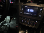
I then connected the module itself and wanted to test it so I connected the rear speaker and one sensor.
I activated the PDC display in module 5F and also coded the PDC module itself.
However, when I put in reverse, the display is working but all the sensors are showing a '!' sign (aka not working). I'm not sure why this is happening, I thought I could atleast see one? Do you have to connect all 10 sensors for it to work? I just wanted to see it in action before I drill holes/rewrite the whole thing.
I'm asking because I wanna make sure it's not a CAN wiring issue. I think my wiring is fine because VCDS is able to read the module and can code it.
EDIT: Another note - the volume control on the infontainment settings screen is working, I can control the tone/volume. So I think the CAN wiring is good or else the ifnotainment wouldn't be able to interact with the speaker?

I figured I should start working in parts as this is a big project so today I started with wiring the module itself.
I started with the CAN wiring. Since there was not much documentation, I had to figure out things on my own. Reaching the CAN gateway was almost impossible. I had to flip my whole body upside down to work down there. I somehow managed to cut the ziptie, untie the wires and then started wiring. The kit came with an extension 3 pin connector, which is used to wire the CAN high/low wires without damaging the original wires. I connected the brown/orange wire to pin 8 and the light blue/orange wire to pin 18.
I then connected the black/green wire as per o_a_ravi's suggestion to fuse 34 using add-a-fuse and also connected the ground (brown) wire to the nearest grounding screwing point.
I then connected the module itself and wanted to test it so I connected the rear speaker and one sensor.
I activated the PDC display in module 5F and also coded the PDC module itself.
However, when I put in reverse, the display is working but all the sensors are showing a '!' sign (aka not working). I'm not sure why this is happening, I thought I could atleast see one? Do you have to connect all 10 sensors for it to work? I just wanted to see it in action before I drill holes/rewrite the whole thing.
I'm asking because I wanna make sure it's not a CAN wiring issue. I think my wiring is fine because VCDS is able to read the module and can code it.
EDIT: Another note - the volume control on the infontainment settings screen is working, I can control the tone/volume. So I think the CAN wiring is good or else the ifnotainment wouldn't be able to interact with the speaker?
Attachments
-
 1598722320201.png4.6 MB · Views: 136
Last edited:
I think you are on the right direction on bench testing the system. Couple of pointers here.
1. CAN connections are available on the TIUL connector right behind trim where your dead pedal goes. You can tap the connections for CAN and Ground here., if that was not too late.
2. The module needs to see all 12 sensors, buttons and the 2 speakers to have a error free operations. That is quite self evident if you do a error log on the park assist module in vcds.
3. Park module makes the alert tones via the 2 buzzers supplied. However it puts in a request to turn down volume to MMI or infotainment via CAN bus., reduction amount can be controlled through long coding and adaptation.
4. You will still have some errors in test mode, whicch can be rectified post final install. Also check the 2 buttons work and the yellow/white illumination. You can also run the basic test option in vcds to check.
Thanks a lot for the reply, o_ravi.
1. It'd probably be better to connect to the TIUL point instead of tapping into the CAN gateway module for convenience. Do you know the exact connector/pins needed?
2. I see. I assume that's why it didn't work in my testing.
3. Thanks for the tip.
4. The kit came with a premade harness for the button set. I connected it in my tests and the button did work (it jumped to the ParkPilot screen when I pressed it) however it doesn't illuminate. The harness for the button comes with a light blue wire that has the same 3 pin extension. Any idea where that goes? Also, for illumination I assume I need to tap into the left side button pins to make it work?
Cuzoe
Autocross Champion
- Location
- Los Angeles
If Fraysa was able to pin the new wiring directly into 8/18 at the Gateway their car may not have have that wiring at the TIUL. As an example, my car does not have extended CAN wiring at the TIUL as it didn't come equipped with anything that would normally be connected to that bus. Either way, sounds like the CAN connection is okay, even it was made the hard way.
As far as the switch... check the wiring diagrams o-a_ravi posted. It lists the wiring connections. You will need all 6 connected for all of the illumination to work. Colors of the harnesses from Ali don't always match but you can go by the pinouts...
Pin 1 - ground and based on the buttons working I assume you connected to a ground (in all my Ali harnesses this one has been the right color, brown)
Pin 3 - momentary ground contact for Parking Aid button (since you said pressing this button works we can assume it's connected)
Pin 4 - momentary ground contact for Parallel Parking Assist (assume same as above)
Pin 6 - power coming from the parking control module to illuminate (orange I assume) the Parking Aid button when active
Pin 7 - power coming from the parking control module to illuminate (orange I assume) the Parallel Parking Assist button when active
***Pins 3-7 are likely wired into connectors on both sides of the provided harnesses. In my experience these colors rarely match the VW wiring diagrams but it doesn't really matter since they are already pinned***
That leaves pin 2 (which is gray in the wiring diagram but maybe it's your light blue wire) This would normally be tied into wiring coming from BCM Plug C pin 62 which is Terminal 58d. Terminal 58d is the the adjustable button lighting for most of the interior (buttons/dash/etc.) This would be the white illumination for your new buttons (when headlights are on) and would adjust with your dimming control.
In my experience, the Ali harnesses that require BCM Terminal 58d wiring usually give you a 3 pin extension harness that lets you tap into pin 10 at the rotary head light switch. Pin 10 on that connector is tied to Terminal 58d. I have seen this wire in light blue in some of the Ali harnesses.
That should give you adjustable white lighting for the buttons on the included button set (including the TPMS Set button). As for (what I assume is) orange illumination, check the long coding and/or adaptations in the parking control module. The power to for those lights comes from that module so there might be a coding/adaptation to tell the module that the orange lights are installed.
It is also possible, even likely, that they work by default (no coding required) but only illuminate orange if the system is engaged and working properly. Since yours isn't fully working yet they might not illuminate. In any case, the orange illumination is independent of the white illumination so even if you don't connect the light blue wire for Terminal 58d the orange should work.
Thanks a lot!
I did mention I used the 3 pin extension connector for the CAN wiring so I did already have the wires there. Anyways, since I already connected it, I don’t wanna go through the hassle of removing it just to use the TIUL point. It was super hard to get to the CAN gateway.
I think you’re right about the light blue wire. It did come with the 3 pin extension. So I basically have to route that wire to the light switch.... sounds a bit complicated.
Anyways thanks for clearing that one out for me!
Any tips about routing cables?
1. How to route the big harness for the rear sensors? Do I just take out the trim on the door sills all the way to the back?
2. How to route the front? UK cars have the left side firewall available but LHD cars have a huge harness on that hole. It’s really hard to poke anything there, let alone a big harness for the Pdc.
When i did this retrofit, the holes through the firewall and through the trunk., the holes with the silicone gourmets were too small to accommodate the phugs. So i had to unpin the plug/socket., fish the wires and repin it again.
Even with the socket pin tool, i broke few pin tabs and order a new socket online on ebay and wait another week for it to arrive. If you are doing it be mindful of the pins and dont exert too much pressure.
Even with the socket pin tool, i broke few pin tabs and order a new socket online on ebay and wait another week for it to arrive. If you are doing it be mindful of the pins and dont exert too much pressure.
Steversonix
New member
- Location
- USA
- Car(s)
- GOLF MK7
As you said. You can trust this seller! ")