golfdave
Autocross Champion
- Location
- Scotland (U.K.)
- Car(s)
- Mk7 Golf GT Estate
Disclaimer:- This info is for community usage. I am NOT affiliated to, or sponsored by, any company/individual to promote them or their products. Companies/individuals may NOT use my name, photos, or threads/technical guides, for financial or personal gain (fraudulent misrepresentation).
Part 1 of 4
Vehicle used in this guide
UK spec, 2014yr model, Mk7 Golf Estate (GSW), GT (Highline) trim, 1.4lt TSI (140PS) CHPA petrol engine, MQ250 6speed manual gearbox, multi-link rear suspension.
Vehicles that this guide is applicable to
Any Mk7 Golfs.
Special thanks to
I would like to thank forum member “DV52” for giving me the tech specs on the door controller modules in answer to my questions! I would also like to thank forum member “kevinm” for posting up the original info in his thread:-
Kev's GTI PP DSG | Page 2 | GOLFMK7 - VW GTI MKVII Forum / VW Golf R Forum / VW Golf MKVII Forum
So why do this post? Mainly to make it easier for search engines to find & to provide a lot more details! Also this is done on a 5dr car, & without the “illuminated door sills”.
Part I
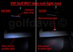
Front, door exit warning lights, on a MK7 Golf
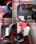
From the technical drawing for the door controllers, Pin16 on the blue 32pin “S004” connector is designated as “Ausstiegs-Warnleuchte”, which translates as “Exit Warning Lamp”. It appears that this pin is on all versions of the driver & passenger, front door controllers. On the GTD/GTI/R, VW use this for the illuminated door sills.
Also we need to connect to a ground pin which again is the same for all versions, Pin5 on the blue 32pin connector, BF_GND (Bedienfeld GND) translates as “Panel GND”.
VW parts list & approx costs in UK £
These are the original previous generation Passat door exit warning lights.
Item:- 1K0 947 411A, Door warning light housing (for incandescent bulb) red/white
Item.:- 1J0 971 972, 2 pin connector housing with directional clip.
This is the current (2015 ->) Passat door exit warning lights.
Item:- 3G0 947 411, LED Door warning light red/white £20.84 (x2)***
Item:- 1H0 972 702 A, 2 pin black connector housing, £3.31 (x2)***
You will need some spare clips, in case you break any. The drawing shows Item No.8 on the top edge near the hinge/mirror side, this is wrong as it is near the opening side furthest away from the hinge/mirror.
Item No.5:- 7L6 868 243, Clip, press/pull type, £0.89 (x4)***
Item No.8:- 3AA 868 246, Clip, slide type, bodywork side of clip, £0.80 (x1)***
You will also need to order VW repair wires (from VW dealer parts dept.). A repair wire is a 0.5m length of wire with the same metal pin/contact at each end
Item:- 000 979 009 E, (A05 wire set) 1.5mm pin, 0.5mm wire, for the door control module 32pin blue connector. (This wire is not needed if you have the factory fitted illuminated door sills GTD/GTI/R). £3.35 (x1)***
Item:- 000 979 019 E, (A05 wire set), 1.5mm pin, 0.5mm wire, for the door LED warning light 2pin connector. £4.57 (x2)***
You also need 4m of 0.5mm2 auto wire (I got 2m purple & 2m brown colours) as “extension wire”, black cable ties, black fabric loom tape (Tesa brand is best). You could use “Scotch-Locks” to connect the cables, or solder & heat-shrink over, but I used special “self soldering” adhesive clear heat shrink joints (just use a hot air gun & heat deflector nozzle/damp cloth to protect surrounding trim).
Info
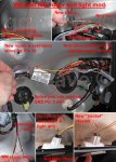
The incandescent bulb light unit (1K0) has a matching directional (one way only) connector (1J0) with the matching locating ridge/tab. This makes sure it can only be inserted one way. The new LED light unit (3G0) still has this locating ridge, however the correct connector for it according to ETKA is the 1H0 version. This connector does not have a locating ridge/tab so can be inserted either way into the LED light unit.
LED’s are polarity sensitive, i.e. they will not work if the “+” & “-“ are swapped around. So why do VW not specify the directional (1J0) connector for the LED light unit? I think that they cannot guarantee from their suppliers which pins on the LED light units will be “+” & “-“, so use the non-directional connector (1H0), so you can just remove, turn 180deg, & re-insert the connector!
Front Door card/trim removal
This applies to all MK7 Golf’s, Hatch, Estate/Variant/Sportswagen, 5dr, 3dr etc.
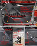
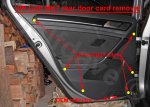
The only difference is that the front doors on the 5dr have a “slide” clip instead of a standard “push/pull” clip in one position, as marked on the photos.
Using a trim remover tool insert into the notch at the top inside front join edge of the internal handle and gently prise apart, going down the length of this front join. Then using a T-star (T-27 size) long reach bit/key undo the two bolts, one just revealed behind this cover, & the other below the handle. Then turn the plastic nut in the recess on the bottom edge of the door card 90deg using a 10mm spanner. Now the hard part! There are several push/pull clips to undo, by using a trim removal tool under the bottom edge of the door card to lever a big enough gap to put your fingers into (use clean cloths to protect the paintwork when using the trim removal tools). Then prise the door card from the door, along the bottom & side edges. Now the top corner on the door card furthest from the hinge is held on with a different “slide” clip, this undoes when you lift the door card up. So now lift the door card up (do not pivot outwards) of this slide clip & the top edge which is clipped in will now undo, lift the door lock side up further, & be carefully around the black plastic triangular trim by the mirror as this requires more force to lift the door card out of the top “clip strip”.
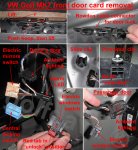
Now the door card is still retained by the electric connections & the “Bowden” cable from the door lock to the door handle. To undo the Bowden cable press the small hoop outwards/away along the main body & the whole mechanism will slide/pivot out. Now undo each electrical connection which tethers the door card to the door, & place the door card to one side.
There may be up to four connectors on the driver’s door & two connectors on the passenger door. The cables for these are short, & the electric window switch connector has to be undone mainly by feel as it is behind the sound-deadening material flap.
Drivers side electrical connections to undo:-
1. Alarm red LED indicator. (has a very small tab which has to be pressed away from the body)
2. Electric mirrors switch. (has a red locking tab which has to be pulled out & then the black tab pressed in).
3. Electric windows switch. (easy, press in tab).
4. Ambient illumination strip (if fitted). (easy, press in tab).
5. Central locking switch. (easy, press in tab).
The electric window switch & the alarm led connectors are difficult on the driver’s door.
Passenger side electrical connections to undo:-
1. Electric window switch. (easy, press in tab).
2. Ambient Illumination strip (if fitted). (easy, press in tab).
Part 1 of 4
Vehicle used in this guide
UK spec, 2014yr model, Mk7 Golf Estate (GSW), GT (Highline) trim, 1.4lt TSI (140PS) CHPA petrol engine, MQ250 6speed manual gearbox, multi-link rear suspension.
Vehicles that this guide is applicable to
Any Mk7 Golfs.
Special thanks to
I would like to thank forum member “DV52” for giving me the tech specs on the door controller modules in answer to my questions! I would also like to thank forum member “kevinm” for posting up the original info in his thread:-
Kev's GTI PP DSG | Page 2 | GOLFMK7 - VW GTI MKVII Forum / VW Golf R Forum / VW Golf MKVII Forum
So why do this post? Mainly to make it easier for search engines to find & to provide a lot more details! Also this is done on a 5dr car, & without the “illuminated door sills”.
Part I
Front, door exit warning lights, on a MK7 Golf
From the technical drawing for the door controllers, Pin16 on the blue 32pin “S004” connector is designated as “Ausstiegs-Warnleuchte”, which translates as “Exit Warning Lamp”. It appears that this pin is on all versions of the driver & passenger, front door controllers. On the GTD/GTI/R, VW use this for the illuminated door sills.
Also we need to connect to a ground pin which again is the same for all versions, Pin5 on the blue 32pin connector, BF_GND (Bedienfeld GND) translates as “Panel GND”.
VW parts list & approx costs in UK £
These are the original previous generation Passat door exit warning lights.
Item:- 1K0 947 411A, Door warning light housing (for incandescent bulb) red/white
Item.:- 1J0 971 972, 2 pin connector housing with directional clip.
This is the current (2015 ->) Passat door exit warning lights.
Item:- 3G0 947 411, LED Door warning light red/white £20.84 (x2)***
Item:- 1H0 972 702 A, 2 pin black connector housing, £3.31 (x2)***
You will need some spare clips, in case you break any. The drawing shows Item No.8 on the top edge near the hinge/mirror side, this is wrong as it is near the opening side furthest away from the hinge/mirror.
Item No.5:- 7L6 868 243, Clip, press/pull type, £0.89 (x4)***
Item No.8:- 3AA 868 246, Clip, slide type, bodywork side of clip, £0.80 (x1)***
You will also need to order VW repair wires (from VW dealer parts dept.). A repair wire is a 0.5m length of wire with the same metal pin/contact at each end
Item:- 000 979 009 E, (A05 wire set) 1.5mm pin, 0.5mm wire, for the door control module 32pin blue connector. (This wire is not needed if you have the factory fitted illuminated door sills GTD/GTI/R). £3.35 (x1)***
Item:- 000 979 019 E, (A05 wire set), 1.5mm pin, 0.5mm wire, for the door LED warning light 2pin connector. £4.57 (x2)***
***=Only these items required from the dealers in my project!***
Other parts required:-You also need 4m of 0.5mm2 auto wire (I got 2m purple & 2m brown colours) as “extension wire”, black cable ties, black fabric loom tape (Tesa brand is best). You could use “Scotch-Locks” to connect the cables, or solder & heat-shrink over, but I used special “self soldering” adhesive clear heat shrink joints (just use a hot air gun & heat deflector nozzle/damp cloth to protect surrounding trim).
Info
The incandescent bulb light unit (1K0) has a matching directional (one way only) connector (1J0) with the matching locating ridge/tab. This makes sure it can only be inserted one way. The new LED light unit (3G0) still has this locating ridge, however the correct connector for it according to ETKA is the 1H0 version. This connector does not have a locating ridge/tab so can be inserted either way into the LED light unit.
LED’s are polarity sensitive, i.e. they will not work if the “+” & “-“ are swapped around. So why do VW not specify the directional (1J0) connector for the LED light unit? I think that they cannot guarantee from their suppliers which pins on the LED light units will be “+” & “-“, so use the non-directional connector (1H0), so you can just remove, turn 180deg, & re-insert the connector!
Front Door card/trim removal
This applies to all MK7 Golf’s, Hatch, Estate/Variant/Sportswagen, 5dr, 3dr etc.
The only difference is that the front doors on the 5dr have a “slide” clip instead of a standard “push/pull” clip in one position, as marked on the photos.
Using a trim remover tool insert into the notch at the top inside front join edge of the internal handle and gently prise apart, going down the length of this front join. Then using a T-star (T-27 size) long reach bit/key undo the two bolts, one just revealed behind this cover, & the other below the handle. Then turn the plastic nut in the recess on the bottom edge of the door card 90deg using a 10mm spanner. Now the hard part! There are several push/pull clips to undo, by using a trim removal tool under the bottom edge of the door card to lever a big enough gap to put your fingers into (use clean cloths to protect the paintwork when using the trim removal tools). Then prise the door card from the door, along the bottom & side edges. Now the top corner on the door card furthest from the hinge is held on with a different “slide” clip, this undoes when you lift the door card up. So now lift the door card up (do not pivot outwards) of this slide clip & the top edge which is clipped in will now undo, lift the door lock side up further, & be carefully around the black plastic triangular trim by the mirror as this requires more force to lift the door card out of the top “clip strip”.
Now the door card is still retained by the electric connections & the “Bowden” cable from the door lock to the door handle. To undo the Bowden cable press the small hoop outwards/away along the main body & the whole mechanism will slide/pivot out. Now undo each electrical connection which tethers the door card to the door, & place the door card to one side.
There may be up to four connectors on the driver’s door & two connectors on the passenger door. The cables for these are short, & the electric window switch connector has to be undone mainly by feel as it is behind the sound-deadening material flap.
Drivers side electrical connections to undo:-
1. Alarm red LED indicator. (has a very small tab which has to be pressed away from the body)
2. Electric mirrors switch. (has a red locking tab which has to be pulled out & then the black tab pressed in).
3. Electric windows switch. (easy, press in tab).
4. Ambient illumination strip (if fitted). (easy, press in tab).
5. Central locking switch. (easy, press in tab).
The electric window switch & the alarm led connectors are difficult on the driver’s door.
Passenger side electrical connections to undo:-
1. Electric window switch. (easy, press in tab).
2. Ambient Illumination strip (if fitted). (easy, press in tab).
Attachments
Last edited:
